


Next: The CCD imager for
Up: The ALIS Imager
Previous: Some basic concepts
Contents
Index
Subsections
Selecting an imager for ALIS
The selection process for an ALIS imager includes many considerations
of scientific, technical as well as of an economical nature.
Naturally this leads to various compromises. A complete ALIS imager
consists of optics, filters and a detector with its electronics and
supporting systems. The choice of detector determines many parameters
of the other imager subsystems, therefore this choice will be
discussed first.
Comparison of an ICCD with a CCD imager
An ICCD imager was considered early on in the ALIS project
[for example Steen et al., 1990] and indeed many excellent CCD imagers for
aurora and airglow, as, for example, the HAARP imager
[Lance and Eather, 1993], the Portable Auroral Imager (PAI)
[Trondsen, 1998] and the new Finnish all-sky camera
[Syrjäsuo, 2001] as well as some of the imagers operated by
Kaila [2003a] are based on an image-intensified CCD. Yet, it is
important to realise that most CCDs have a higher  than that of
the photo-cathode in an image-intensifier. For example, the PAI, used
for high spatial and temporal resolution auroral imaging, have a
than that of
the photo-cathode in an image-intensifier. For example, the PAI, used
for high spatial and temporal resolution auroral imaging, have a
 of 67 %, while the quantum efficiency of the
photo-cathode is only 28%, both at
of 67 %, while the quantum efficiency of the
photo-cathode is only 28%, both at
 Å
[Trondsen, 1998, p. 51]. Scientific grade CCDs might have a
of up to about 90% as demonstrated in Figure 3.1. Despite
this a CCD is not always preferable to an ICCD.
Å
[Trondsen, 1998, p. 51]. Scientific grade CCDs might have a
of up to about 90% as demonstrated in Figure 3.1. Despite
this a CCD is not always preferable to an ICCD.
Figure 3.2 plots
 as a function of column
emission rate,
as a function of column
emission rate,
Figure:
vs. column emission,
for f/3.9 optics with
 and 16.7 ms on-chip integration time.
(a) Ideal photon detector (Equation 3.29) with
and 16.7 ms on-chip integration time.
(a) Ideal photon detector (Equation 3.29) with
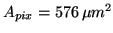 (ALIS).
(b) Equation 3.28 for ALIS ccdcam5 (Table 3.2).
(c) Same as (a) but
(ALIS).
(b) Equation 3.28 for ALIS ccdcam5 (Table 3.2).
(c) Same as (a) but
 (PAI).
(d) Equation 3.38 for the PAI ICCD (Table 3.1).
(e) Same as (b) but for the PAI CCD without image intensifier.
The horizontal line indicates the threshold of detection at
(PAI).
(d) Equation 3.38 for the PAI ICCD (Table 3.1).
(e) Same as (b) but for the PAI CCD without image intensifier.
The horizontal line indicates the threshold of detection at
 .
.
|
|
with
 and a fixed integration time of 16.7 ms (NTSC video
standard). The CCD data were taken from the technical specifications
for the PAI (Table 3.1) as well as from the
specifications for an
and a fixed integration time of 16.7 ms (NTSC video
standard). The CCD data were taken from the technical specifications
for the PAI (Table 3.1) as well as from the
specifications for an
Table 3.1:
ICCD parameters for the portable auroral imager (PAI) obtained from
Trondsen [1998, Table 4.1 p.51].
All values at room temperature.
Notes: a) Value from data-sheet of the CCD.
b) Trondsen has confirmed the value of
 to be a typo.
|
Parameter |
Symbol |
PAI |
Unit |
Notes |
|
MCP mean gain (medium) |
 |
1500 |
|
|
|
Photo-cathode dark-current |
 |
0.1 |
 |
|
|
Photo-cathode quantum efficiency |
 |
28 |
% |
at 5577 Å |
|
CCD read noise |
 |
80 |
 |
|
|
CCD dark current |
 |
0.1 |
 |
b) at
 |
| CCD full well (anti-blooming off) |
 |
80 |
 |
a) |
|
CCD quantum efficiency |
|
67 |
% |
at 5577 Å |
|
CCD pixel area |
 |
 |
 |
|
|
Fibre-optic minification ratio |
 |
1.55 |
|
|
|
ALIS imager (ccdcam5, Table 3.2). Ideal photon
Table 3.2:
Some parameters for the CCD in ALIS-imager
ccdcam5 (SI-003AB serial No. 6144GBR10-B2) as measured by the CCD-manufacturer. All values measured at
 unless otherwise noted. Notes: a) quadrant with highest value. b) same parameter, as measured by camera manufacturer.
c) quadrant A 3% linearity.
d) questionable assuming a lower value of about 85% (Figure 3.1) [author's note].
(See also Tables B.1-B.6 in Appendix B)
unless otherwise noted. Notes: a) quadrant with highest value. b) same parameter, as measured by camera manufacturer.
c) quadrant A 3% linearity.
d) questionable assuming a lower value of about 85% (Figure 3.1) [author's note].
(See also Tables B.1-B.6 in Appendix B)
|
Parameter |
Symbol |
ccdcam5 |
Unit |
Notes |
|
Read noise |
|
8.3 |
|
a) b)
 |
|
Dark current |
|
12.4 |
 |
at
 . . |
|
Full well |
 |
316 |
|
c) |
|
Quantum efficiency |
|
89.8 |
% |
4000 Å |
|
Quantum efficiency |
|
98.9 |
% |
5500 Å, at
, d). |
|
Quantum efficiency |
|
99.4 |
% |
7000 Å, d). |
|
Quantum efficiency |
|
55.3 |
% |
9000 Å |
|
detectors with the same pixel area as of the ALIS Imager (a) and the
PAI (c), have thresholds of detection at approximately 20 kR and
40 kR respectively. The ALIS Imager, curve (b), reaches
at
about 100 kR which is also the case for the PAI ICCD (d). Curve
(e) for the unintensified CCD of the PAI (without image intensifier)
does not reach
until at approximately 2 MR. Clearly, this CCD is not
suitable for low-light observations, without image intensifier. These
results are in agreement with Trondsen [1998, Chapter 4].
At low column emission rates, the ALIS Imager and the PAI ICCD appear
comparable in
. However, note that this is a misleading result,
as the PAI ICCD, with its frame-transfer CCD, provides data at NTSC
video rates (
 ), while the read-out of the ALIS
quad read-out full-frame CCD is limited to about 2.8 s at the stated
read noise, resulting in a maximum frame rate of about 0.3 frames/s
(see Table 3.3 in Section 3.2.2). Therefore, as
already noted by Trondsen [1998] it might be concluded that
the ICCD is the better choice for temporal resolutions
), while the read-out of the ALIS
quad read-out full-frame CCD is limited to about 2.8 s at the stated
read noise, resulting in a maximum frame rate of about 0.3 frames/s
(see Table 3.3 in Section 3.2.2). Therefore, as
already noted by Trondsen [1998] it might be concluded that
the ICCD is the better choice for temporal resolutions  needed by the high temporal resolution requirements on the PAI.
While the CCD is a linear device, the image-intensifier is an
electron-tube exhibiting non-linearities and aging effects making the
already non-trivial task of absolute calibration even more
complicated. Also image-tubes might bloom, causing the entire image to
saturate, if part of the scene within the field-of-view saturates.
Exposure to too bright point sources might lead to permanent image
retention or intensifier damage [See for example Holst, 1998, and references
therein]. For these reasons it was decided to further
investigate the feasibility of using an unintensified CCD for the ALIS
imagers. However, for such a system to be useful for studies of
aurora and airglow, the unintensified CCD must provide acceptable
for column emission rates down to a couple of hundred Rayleigh,
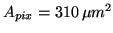
for integration times of about 1 s. Figure 3.3
Figure:
versus integration time for
(a) 1 MR IBC-IV (b) 100 kR IBC-III, (c) 10 kR IBC-II, (d)
1 kR, IBC-I and (e) 100 R. All at 5577 Å.
|
|
displays the
plotted versus integration time for column
emissions ranging from 100 R-1 MR. As seen IBC-I-IV have
acceptable
for 1 s integration time. Examining Equation 3.28, it is
seen that the
can be increased by increasing the number
of photoelectrons, i.e. by increasing the pixel area, improving the
transmittance, increasing the integration time, or by improving the
quantum efficiency (see Equations 3.20 and 3.22). One possibility is to
utilise on-chip binning factors (``super-pixels'') to increase the
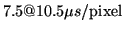
pixel area as demonstrated in Figure 3.4.
Figure 3.4:
SNR vs. column exposure rates at 1 s integration time (
 ) with binning factors: (a)
  , (b)
, (b)
 , (c)
, (c)
 , (d)
, (d)  and (e)
 .
.
|
|
As seen, the threshold of detection improves by the product of the
binning factor (i.e. the increase of pixel area). On the other hand,
the spatial resolution is decreased by the same factor. This also
implies that the frame-rate increases, as there are less pixels to
read-out. Thus, for any given measurement situation, application of
on-chip binning factors provides a way to optimise a compromise
between sensitivity, spatial and temporal resolution.
For high column emission rates the CCDs saturate after reaching their
charge well-capacity. It should be noted that pattern noise is not
taken into account in the plots. This noise would have decreased the
somewhat at high-signal levels, but is of little interest for
photon-limited imaging situations.
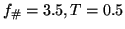
Frame rate
The ALIS CCD is a full frame CCD. The read-noise (which increases
as the square-root of the pixel-rate, mainly due to the 1/f-noise, see
Section 3.1.7) in Table 3.2 was measured at a pixel
read-out rate of
 . At this rate it would
take 11 s to read
. At this rate it would
take 11 s to read  pixels. One way of getting around this
problem is to divide the CCD into sub-arrays. The ALIS CCD is divided
into four sub-arrays with identical read-out channels working in
parallel (Figure 3.5).
pixels. One way of getting around this
problem is to divide the CCD into sub-arrays. The ALIS CCD is divided
into four sub-arrays with identical read-out channels working in
parallel (Figure 3.5).
Figure 3.5:
At a given pixel rate, a full frame CCD (left) takes four times as long to read-out as compared to an array divided into four sub-arrays (right), each with its own serial read-out register, sense node, amplifiers, S/H circuits and ADC:s.
|
|
Table 3.3 illustrates the maximum achievable read-out
rates for the ALIS CCDs.
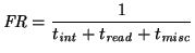
The frame rate,
 , as a function
of on-chip integration (``exposure'') time,
, as a function
of on-chip integration (``exposure'') time,
 ,
read-out time,
,
read-out time,
 , and misc. time
before the next image can be read,
, and misc. time
before the next image can be read,
 , (for example caused by
the electronics, or the need to flush the CCD etc.) is given by:
, (for example caused by
the electronics, or the need to flush the CCD etc.) is given by:
 |
(3.43) |
Next: The CCD imager for
Up: The ALIS Imager
Previous: Some basic concepts
Contents
Index
copyright Urban Brändström
![\includegraphics[]{eps/octave/snrpaialis1.eps}](img238.png)
![\includegraphics[]{eps/octave/snrtexp.eps}](img260.png)
![\includegraphics[]{eps/octave/snrbinning.eps}](img261.png)
![\includegraphics[]{eps/imager/quad.eps}](img270.png)