 |


Next: The Forward model -
Up: Geometrical calibration of ALIS
Previous: Calibration methods
Contents
The following example shows that the suggested calibration scheme gives the
required accuracy.
Figure 4.6:
Fit between star positions from sky map and the star positions
found in the
image.  's are the calculated positions of the stars with
the rotations and optical parameters found from optimisation
and the 's are the calculated positions of the stars with
the rotations and optical parameters found from optimisation
and the  's are the positions of the stars in the image.
As can be seen there are only very small deviations between the marker pairs. 's are the positions of the stars in the image.
As can be seen there are only very small deviations between the marker pairs.
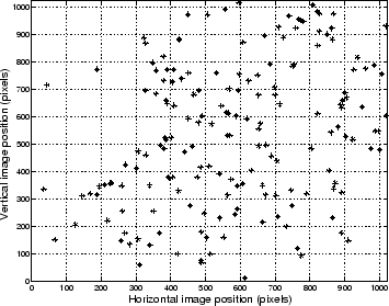 |
Figure 4.6 shows a plot of the star positions found in the
image and those projected from the sky map onto the image using the
optical transfer function. The overall fit between the ``image
stars'' and the ``catalogue stars'' is good. To prove quantitatively
that the accuracy requirement is met we have to prove that the
distribution of the errors has a width corresponding to less than
0.02. This is equal to 1/3 of a pixel field-of-view.
Figure 4.7:
Here the two-dimensional error between the stars in the image and
the projection of the star catalogue with the optimal optical
parameters is plotted. Clearly the spread is essentially
confined to one pixel width.
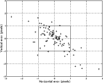 |
The scatter plot of the errors shown in
figure 4.7 shows that only a few errors excede
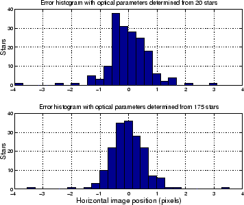
 pixel. Finally we compare the histograms
of the radial error with optical parameters determined from 20
identified stars and optical parameters determined from 175 identified
stars. As can be seen in Figure 4.8 the error
distribution becomes a bit narrower as the number of stars increase
when the optical parameters are determined. The width is less than a
pixel for both cases but narrower in the lower panel, and there are
less outliers due to the fact that the larger number of stars is more
evenly distributed over the image. pixel. Finally we compare the histograms
of the radial error with optical parameters determined from 20
identified stars and optical parameters determined from 175 identified
stars. As can be seen in Figure 4.8 the error
distribution becomes a bit narrower as the number of stars increase
when the optical parameters are determined. The width is less than a
pixel for both cases but narrower in the lower panel, and there are
less outliers due to the fact that the larger number of stars is more
evenly distributed over the image.
Figure 4.8:
Top panel: The radial error histogram of 175 stars
with optical parameters determined from optimisation with
20 identified stars.
Lower panel: The radial error histogram of 175 stars
with optical parameters determined from optimisation with
all 175 identified stars.
 |
Next: The Forward model -
Up: Geometrical calibration of ALIS
Previous: Calibration methods
Contents
copyright Björn Gustavsson 2000-10-24
|