next up previous contents
Next: Calibration methods Up: Geometrical calibration of ALIS Previous: Introduction and overview   Contents

System and requirements

Currently ALIS is equipped with cameras with a resolution of 1024 by 1024 pixels and a field-of-view of approximately $ 57$. This implies that the field-of-view of a pixel is approximately $ 0.06$. A reasonable requirement for pixel line-of-sight accuracy is $ \pm0.02$. Little benefit would be gained from a significantly more accurate determination and a less accurate determination will not utilise the image resolution in an optimal way. For an optical system with higher angular resolution there is a corresponding increase in the accuracy requirements.

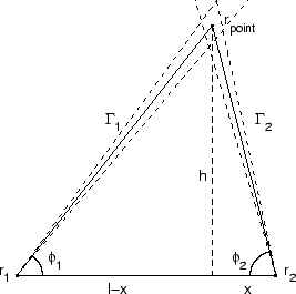
A first order error analysis is easily accomplished if we look at stereoscopic triangulation of an object point found in two images from sites at $ \bar{r}_{1}$ and $ \bar{r}_{2}$, respectively (Figure 4.1).

Figure 4.1: Definitions of the parameters used in equation (4.1) and equation (4.2).
\begin{figure}
		    \centering \epsfxsize =6.cm
		    %\mbox{\epsffile{../Figures/error_tri2.ps}}
		    \mbox{\epsffile {Figures/error_tri2.ps}}
		    \end{figure}

If we let the two lines-of-sight $ \Gamma_1,\Gamma_2$ be described by their angles $ \Phi_1,\Phi_2$ relative to the vector $ \bar{r}_{1} -
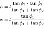
	    \bar{r}_{2}$, it is straightforward to calculate the uncertainty in the position of $ \bar{r}_{point}$ due to errors in the line-of-sight parameters $ \Delta\Phi_1,\Delta\Phi_2$ and the station separation $ \Delta l$. To make the analysis clear, and to simplify the algebra, we assume that the line-of-sight vectors and the locations of the two stations lie in a plane and that the line-of-sight errors are in the same plane, giving us a two-dimensional geometrical problem to solve. The simplified problem is to determine uncertainty in the position of the top apex of a triangle given the base length $ (l\pm{\Delta}l)$ and two angles $ (\phi_1\pm{\Delta}\phi_1,\phi_2\pm{\Delta}\phi_2)$. Simple trigonometry gives:

\begin{displaymath}\begin{aligned}h &= l\frac{\tan\phi_1\cdot\tan\phi_2}{\tan\ph...
		    ...\  x &= l\frac{\tan\phi_1}{\tan\phi_1+\tan\phi_2} \end{aligned}\end{displaymath}

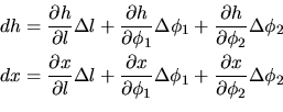
where the parameters are defined as shown in Figure 4.1. The sensitivity of $ h$ and $ x$ to errors in $ l,\phi_1$, and $ \phi_2$ is then estimated by the full differentials:

\begin{displaymath}\begin{aligned}dh &= \frac{\partial h}{\partial l}\Delta l +\...
		    ...1 +\frac{\partial x}{\partial \phi_2}\Delta\phi_2 \end{aligned}\end{displaymath}

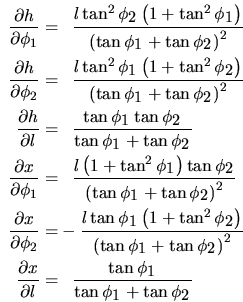
which can be expanded by calculating the partial derivatives:

\begin{displaymath}\begin{aligned}\frac{\partial{h}}{\partial{\phi_1}} = &\phant...
		    ...tan{\it\phi_1}}{\tan{\it\phi_1}+\tan{\it\phi_2}}} \end{aligned}\end{displaymath}

From these equations it is possible to calculate the propagation of uncertainties in the lines-of-sight to the positions for all directions. As a rule of thumb, as the station separation is small compared to the distance to the object, i.e. $ \vert\bar{r}_1-\bar{r}_2\vert\rightarrow0$ the sensitivity in the determination of positions to errors in the direction of the lines-of-sight increase rapidly.

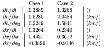
In order to estimate the orders of magnitude of the derivatives, two examples with typical values for stratospheric (case 1) and auroral (case 2) work are given in table 4.1.


Table 4.1: Where the parameters defined in Figure 4.1 for case 1 are: $ l = 50 km, \phi _1 = 30, \phi _2 = 50$ and for case 2: $ l = 50 km, \phi _1 = 60, \phi _2 = 80$.
\begin{table}
		    \centering \begin{tabularx}{80mm}{X\vert XX\vert X}
		    \hline
		    \mu...
		    ...ial\phi_2\)& -0.3896 & -0.9146& \((km/)\)\\
		    \hline
		    \end{tabularx} \end{table}


As can be seen from equation (4.2) and table 4.1, the requirements on the parameter accuracy to obtain the estimated distances to within 50 m are, for auroral studies, of the order of 50 m for the baseline separation, $ {\Delta}l$, and $ 0.02$ for the angular accuracy, $ ({\Delta}\phi_1,{\Delta}\phi_2)$; for stratospheric studies the requirements are less strict.


next up previous contents
Next: Calibration methods Up: Geometrical calibration of ALIS Previous: Introduction and overview   Contents

copyright Björn Gustavsson 2000-10-24